Signature Management

Thermal Deception Field — infrared and radio frequency

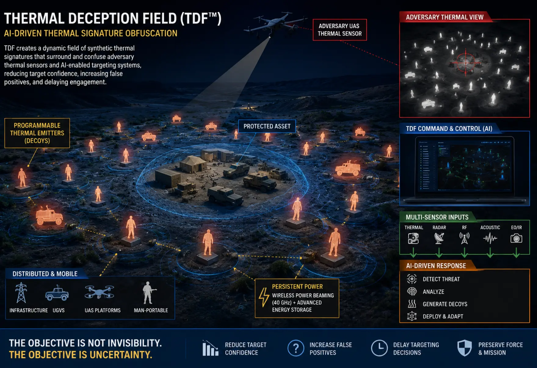
The objective is not invisibility. The objective is uncertainty. TDF surrounds a protected asset with a controlled abundance of convincing false signatures across the infrared and RF spectrum, degrading the confidence of automated targeting systems.

Concept & system design — to be proven

The problem

Thermal imaging is now the default targeting sensor of the modern battlefield.

Low-cost thermal cameras ride on FPV drones, loitering munitions, and persistent ISR platforms. Because thermal sensors read emitted heat rather than reflected light, they reveal bodies, engines, electronics, and generators with little regard for cover or camouflage — and the capability is no longer limited to advanced militaries.

Paint, netting, and terrain masking try to hide a signature that automated target recognition is increasingly good at finding. TDF takes the opposite approach: rather than hide the real signature, it surrounds it with hundreds of plausible false ones and forces every hostile targeting decision to cost more, take longer, and be wrong more often.

Thermal Deception Field concept: programmable thermal emitters surrounding a protected asset, adversary thermal view, TDF command and control, multi-sensor inputs, and AI-driven response.

Two spectra

Infrared and radio frequency, orchestrated as one deception environment.

IR

Infrared deception

  • Programmable thermal emitters rendering personnel, vehicle, generator, and command-post signatures
  • Thin-film graphene heaters modulating 8–14 µm emission — idling diesel, running generator, moving transport
  • LWIR micro-optics (HDPE Fresnel) to widen and soften the obscured region relative to a flat blocker
  • Continuous, randomized pattern variation to resist adversary model learning

RF

Radio-frequency deception

  • DRFM transponders that capture an interrogating radar pulse and re-radiate an altered amplitude/phase return
  • Multiple high-RCS false tracks injected along the threat line of sight, inflating track counts
  • RF, acoustic, and radar decoys de-conflicted with electronic warfare and communications deception
  • Non-Part-15 emission only under FCC licence or Special Temporary Authority; spectrum coordinated with the Government

Architecture

Five cooperating layers.

L1

Distributed emitters

Programmable thermal emitters on fixed infrastructure, mobile platforms, and soldier-emplaced devices. Each can render the signature of a person, vehicle, generator, comms node, logistics stack, or command center on command.

L2

AI signature engine

Edge AI composes synthetic patterns conditioned on terrain, time of day, weather, and known enemy sensor characteristics — deliberately varied to defeat pattern recognition.

L3

Distributed sensor network

Co-located sensors monitor drone activity, RF emissions, thermal imagery, acoustic signatures, and radar. Fusion runs locally so the field acts when reach-back is denied.

L4

Autonomous response

On detection of hostile ISR the field responds in seconds: activating decoys, morphing patterns, spawning moving thermal targets — without an operator in the loop.

L5

Multi-domain integration

Thermal deception synchronized with electronic warfare, GPS spoofing, radar and acoustic decoys, communications deception, and UAV swarms.

Operational concept

Disrupting the adversary kill chain.

Traditional battlefieldThermal deception battlefield
Enemy drone detects a thermal targetEnemy drone detects 500 thermal targets
Identifies a humanCannot distinguish the authentic target
Tracks the humanAI confidence degraded
Engages the humanTargeting solution delayed
Fast, confident, successful engagementMission effectiveness reduced; munitions wasted on phantoms

TDF-A — airborne layer

Angular occlusion: field-scale deception with tens of aircraft, not thousands.

A screen does not need to cover the site — it only needs to occupy the solid angle the site subtends at the adversary's sensor. For a sensor at 15,000 ft AGL at a 45° look-down angle (slant range ≈ 6,466 m) protecting a 200 m × 200 m site with 2 m × 2 m screens, the required standoff is r ≤ 64.7·√N metres. Fifteen aircraft at roughly 250 m from the threat sensor subtend the same solid angle as flat overhead coverage requiring ten thousand.

Screens (N)Total screen areaMax standoff from sensorEquivalent flat-sheet count
1040 m²205 m10,000
1560 m²250 m10,000
25100 m²323 m10,000
50200 m²457 m10,000

The constraint is stated rather than buried: standoff scales only as the square root of aircraft count, so the cluster must operate hundreds of metres from the threat and hold geometry against a manoeuvring platform. One cluster protects against one sensor on one vector.

Maturity

Presented as a concept and design, not a fielded product.

SubsystemEst. TRLBasis / remaining work
Integrated TDF system2Concept and design only; to be proven through prototyping and field test
Edge AI compute & inference3–4General edge compute exists; on-node deception processing to be proven
AI thermal-signature models2–3New models; to be trained against representative sensor data
Programmable thermal emitters5–6Signature decoys exist; networked programmability to be developed
Graphene thin-film heaters3–4Films exist; airborne signature modulation to be demonstrated
DRFM transponders6–7Mature EW technique; Group 1 SWaP integration and authorization remain
40 GHz power beaming3–4Directed mmWave power; field ranging and safety to mature
Ruggedized energy storage8–9Commercial cells; ruggedized integration remains

Phase I — Feasibility

Define threat sensor models, develop synthetic thermal generation on representative edge hardware, and bench-demonstrate a small emitter cluster against representative thermal imagers.

Phase II — Prototype

Build a multi-node field with autonomous response, integrate wireless power beaming and ruggedized storage, and conduct an instrumented field demonstration against fielded UAS/ISR threats.

Phase III — Transition

Harden, scale, and transition to operational users; extend multi-domain integration and pursue dual-use civilian infrastructure protection.

Next step

Start with a scoping study

Six to eight weeks, fixed price. You receive the concept of operations, the Interface Control Document, the electrical and thermal budget against your actual platform, a safety framework, and a firm price for the build.

If the study does not earn the next phase, you have learned that for the cost of a study.

Request a scoping study