Zone 1
Platform interface
Common mechanical datum. Mount points, load paths, roof and underbody attachment, centre-of-gravity envelope, ingress protection. The OEM builds to this once.
Architecture
The Interface Control Document
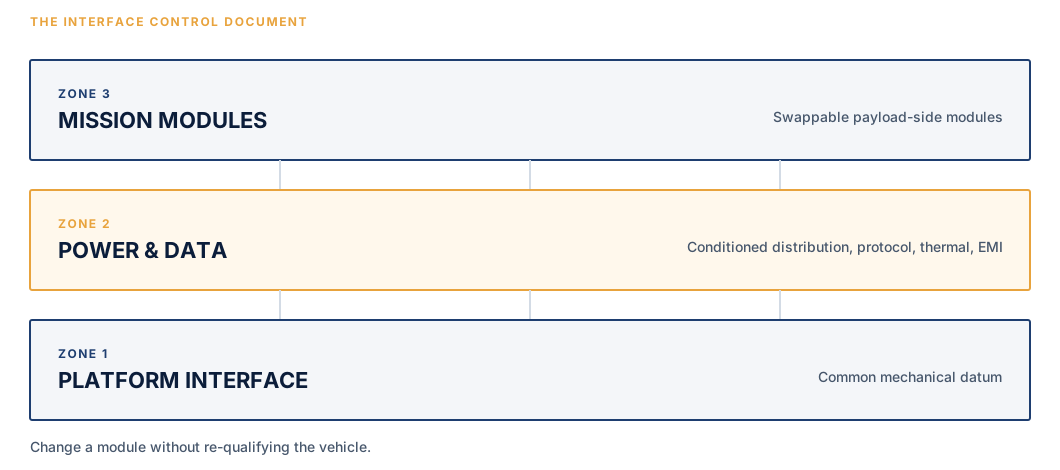
Zone 1
Common mechanical datum. Mount points, load paths, roof and underbody attachment, centre-of-gravity envelope, ingress protection. The OEM builds to this once.
Zone 2
Conditioned DC distribution, alternator budget allocation, backup power, protocol handling, time synchronisation, thermal management, EMI boundaries.
Zone 3
Swappable payload-side modules, each qualified against Zones 1 and 2. Change a module without re-qualifying the vehicle.
Kits install to a fixed datum. No per-vehicle engineering.
Change any vendor without re-engineering the platform.
One documented configuration that survives sustainment and audit.
Power & data architecture
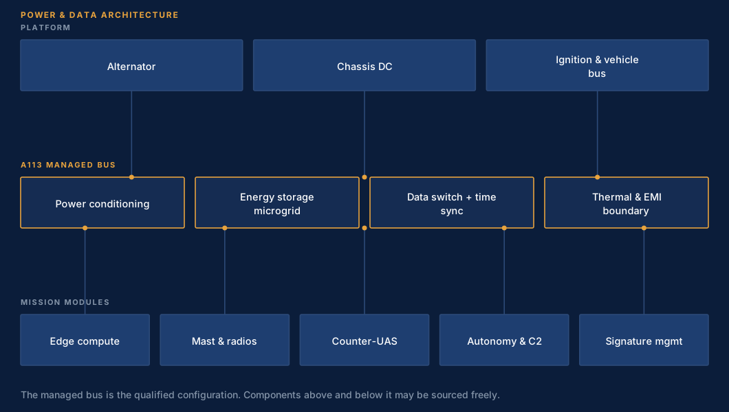
The managed bus is the qualified configuration. Components above and below it may be sourced freely.
Conceptual kit layout
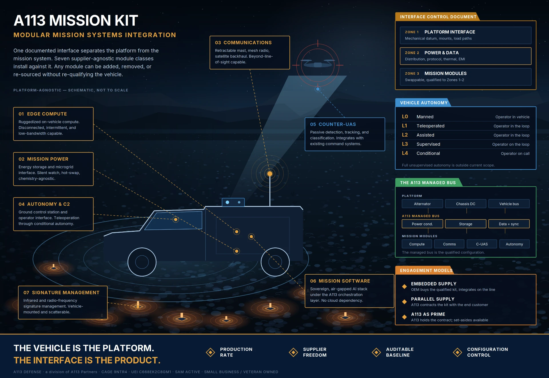
A
Counter-UAS array, EO/IR, GNSS
B
Mesh and satellite backhaul
C
Interior rack, mission software
D
Storage and microgrid interface
E
Vehicle-mounted and scatterable
Side elevation — schematic, not to scale. Final geometry and electrical allocation are established by a paid scoping study on each platform.
Next step
Six to eight weeks, fixed price. You receive the concept of operations, the Interface Control Document, the electrical and thermal budget against your actual platform, a safety framework, and a firm price for the build.
If the study does not earn the next phase, you have learned that for the cost of a study.
Request a scoping study